3.3 Volumetric Fog
3.3.1 Introduction
The traditional form of fog that is supported by the majority of 3D accelerator cards is applied to the whole scene. Whilst the standard technique has some problems, it is fine for outdoor scenes such as in flight simulators. However, applying fog to the whole scene can be too much of a limitation. What if you want to simulate ground fog to add atmosphere to a graveyard scene? What if you want to add a steam filled room to your building? These cases require the application of volumetric fog.
3.3.2 Possible Solutions
So we require a rendering technique to apply volumetric fog to a particular area of a scene. There are several possibilities that spring to mind, the options that I considered were adapting the use of the hardware fog support, using particles and using fog panels.
If the hardware fog support could be used then the performance hit of volumetric fog would be small. The technique would require the application to calculate the required amount of fog at given vertex and then change the fog parameters such that the hardware would arrive at the same value. However, changing the fog parameters during the rendering of a scene is not a feature that is currently supported by most 3D cards so it is not a viable option. These problems can be solved using the EXT_fog_coord extension but this is not widely supported yet.
On the face of it particles are a promising solution to the problem, after all fog is caused by smoke or water particles in the real world. However, when rendering the fog it quickly becomes apparent that the technique isn't going to work. There are two main problems. The first is that the number of particles that are required to render the fog without any noticeable gaps between them is so huge that it is beyond the capability of current PC technology. The second is that the rendering of such a large number of particles leads to a large number of rendering passes for each pixel, the resulting rounding errors (even in 32 bit) lead to some very ugly artefacts.
The solution that works on most platforms and is used in most games, including Corridors of Power, is to use fog panels. This technique uses an extra rendering pass in which a panel set to the required fog colour is blended onto the scene panels that require fogging.
3.3.3 Calculating the Fog Parameter
Before discussing how to render volumetric fog it is worth reviewing the calculation and application of fog in computer graphics. Fog is applied to a pixel by blending it with a pixel set to the fog colour. The amount of blending depends on the value of the fog blending factor which in turn depends on the distance between the viewer and the pixel. In OpenGL, the convention is that the fog blending factor, f, tends from one to zero with increasing distance. Three fog calculation methods are supported:


where z is the distance through the fog. The two basic forms are linear fog (1) and exponential fog (2) & (3). As usual there is a trade-off between realism and performance hit, although hardware support removes the latter.
3.3.4 Rendering Fog Panels
The rendering technique used in volumetric fog involves an extra rendering pass and so is similar to lightmapping. The main difference is that the fog panel uses solid colours with gouraud shading rather than a predefined texture. For all vertices on a given panel, the colour is set to the fog colour for the volume. Then for each vertex, the fog blending factor is calculated and used as the alpha component. The fog panel is then blended over the corresponding scene panel using a suitable blending function. The steps required to render a fogged panel in Corridors of Power are summarised below:
It is important to note that the success of this rendering technique is reliant on two main features. The first is that gouraud shading is required to interpolate the fog colour across the surface of the panel and so it must be enabled. The second is that the gouraud shading will break down if the scene is made up of large panels, therefore all scene panels must be sufficiently subdivided. The subdivision of panels is a trade-off between quality and speed. In Corridors of Power I have found that a maximum panel size not much more than the height of the player is sufficient.
3.3.5 Calculating the Fog Blending Factor
The final piece in the jigsaw is the calculation of the fog blending factor which is in fact the most difficult step. One of the main problems is that the algorithm is entirely dependant on the effects you want to simulate, the accuracy you require and the complexity you require. With volumetric fog the choices you make can be very important because the fog blending factor has to be calculated for each vertex in the scene and if you are not careful you can quickly end up with more floating point calculations than the processor can cope with. This section will describe some of the cases that need to be covered in the algorithm and suggests ways to solve them.
In order to calculate the fog blending factor some modifications are required to the standard fog equations. The exponential equations (2) and (3) are fine because they are based upon the distance through the fog, z. However, the linear equation (1) is not directly applicable because the start and end values would also need to be calculated for every vertex. We therefore simplify (1) for the volumetric case as follows:

where density in this case is the distance at which a pixel would be totally fogged. Note that the computed value of f must be clamped to the range [0,1].
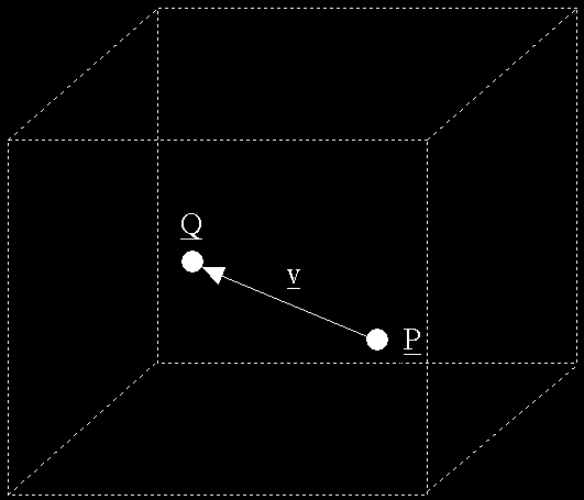
The simplest case in volumetric fog calculations is where the viewer and vertex are both within the same fog volume, as shown in the figure below.

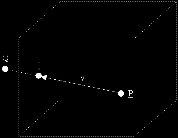
In this case the fog distance, z, is simply the length (i.e. magnitude) of the vector, v, that connects the view position, P, to the vertex position, Q. The next case is where either the viewer or the vertex is inside the fog volume and the other is outside. We will consider the case where the viewer is inside the fog volume as shown in the figure below, although a very similar solution is applicable to the other case.

This situation is a little more complicated because we must consider how the vector between the two points interacts with the fog volume that we have described. If we limit a fog volume to having just one bounding plane, it is fairly straightforward to determine z as the range from P to the intersect point I, (see the section on Collision Detection for the maths to do this). If we have more than one plane then the task becomes more complex because we must determine which plane is intersected and determine the range to the intersect point.
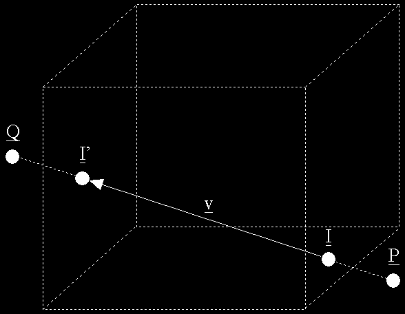
The final case is more complex and covers the case where both the viewer and the vertex are not in the fog volume as shown in the following figure.

This is where things start to get complicated. The first thing we need to decide is whether the vector v intersects the fog volume at all, in which case there is of course no fog. If not then we need to determine the two planes the vector intercepts and determine the intercept points I and I'. Once we have the two intercept points the fog distance z is the magnitude of the vector between them.
3.3.6 Performance Tweaks
From the preceding section it is clear that the amount of processing involved in the calculation of the fog blending factor is huge and we didn't even consider the case where there are two or more separate fog volumes in view! It is clear that limitations may need to be imposed in order to minimise the frame rate hit.
One easy simplification is to limit fog volumes to have only one bounding plane. This limits the effect to things like ground fog or fogging of areas that are at the edge of your scene. This still allows a fair amount of scope for the use of volumetric fog without too much heavy number crunching.
Another possibility is to pre-calculate the fog blending factors for vertices that are static in the scene. This can be used for areas that the viewer can see but can't get into, like low ground fog, or areas where the errors in the fog calculations as the view changes aren't too noticeable.
A final big saving can be made on objects. In a lot of cases the fog blending factor need only be calculated for the object's position rather than all the object's vertices. If the object is quite large it can be split into smaller components and the factor calculated for each component. Either way will give a huge saving compared with applying fog calculations to all the object's vertices.